The topic of receiving capabilities is often discussed (mostly complained about), but rarely seems to focus on the details needed to achieve rewarding gains. The following information as presented is specifically applicable to my experiences with the demanding requirements of 2m / 144MHz EME, but could easily related to similar applications.
While I do not consider myself to be an authority on the topic, I have had lengthy discussions with a large number of people who I do consider to be experts and I have studied all the pertinent material that I could find. I have used this information to optimize my 2m / 144 MHz EME station to the point that I am finally satisfied with it's performance. I can now randomly work a single yagi station (with big power!) off the moon with relative ease. The following information should serve as a step by step guide as I believe the optimization process should be followed as well as a compendium of useful reference information.
Nothing is for free, a lot of hard work is required to achieve more than average success at optimizing a system for the task of EME communications. I was so busy trying to build a competitive VHF contest station that I was always far too busy to focus on the really important details associated with any one band. Like the old saying goes, "jack of all trades, master of none!". I sold all my equipment for 50MHz, 222MHz, 432 MHz, 903 MHz, 1296 MHz, 2304 MHz, 3456 MHz, and 10 GHz to clear my backlog of incomplete projects, reduce the continuous maintenance workload, and eliminate compromises to allow me to FOCUS on my favorite band and the tasks associated with optimizing it's performance.
I could rarely hear 2m EME stations smaller than ones running the legal power limit with 4 long yagis. With this barrier, one quickly runs out of potential contacts. By simply examining the logs of the big guns, it was obvious that smaller stations were constantly around and I simply couldn't hear them. WHY NOT? I had previously moved out of the city (only 5 -10 miles) in an attempt to eliminate sources of local interference (power lines, transformers, household gadgets, etc), so how come I still couldn't hear much better? Well, that is the definition of problem, isn't it!
There seems to be many common myths surrounding amateur radio equipment that tends to make the optimization of a system more difficult than it really is.
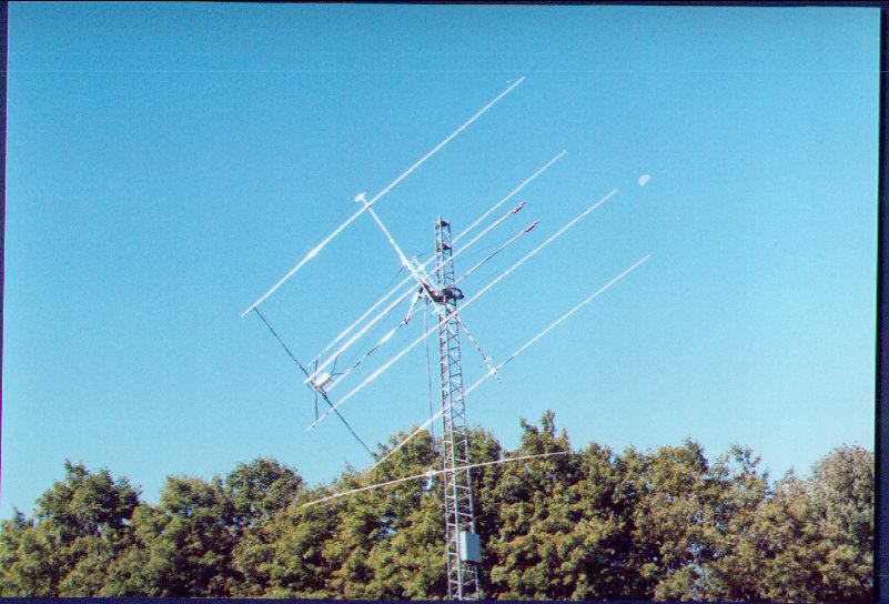
This one was the the biggest culprit for me. I always assumed that if I bought the best that money could buyI would automatically have an optimized station by default. WRONG. I combined excellent antennas (M^2 2M28XP), an expensive tower mounted preamp (SSB Electronics LNA145), low loss feedlines (Andrew Heliax & Superflex, LMR400), a high performance transverter (SSB Electronics LT2S 144MHz - 28 MHz), and a top notch IF rig (Yaesu FT-1000D). .....
Not only does a tower mounted preamp NOT solve all your problems, it creates many more. While it is true that one is essential to any high performance system, a thorough understanding of Noise Figure and all receiving system components capabilities must be had to ensure that an optimum implementation is achieved.
It is true that only the first few components in a receiving string contribute to the overall figure. As such, it is improtant to minimize losses before the first 2 stages of amplification. In my original setup, I had 250' of not so great feedline between my tower mount preamp and transverter which I later found to be significantly increasing my overall system NF.
In most cases, the manufacturer labels their preamp as being band specific. This does NOT mean that the preamp does not amplify throughout the rest of the spectrum. Everyone is very concerned with the advertised gain and NF of a preamp. I used a Hewlett-Packard Network Analyzer to sweep a number of the industry favourites (no names mentioned!) from .1MHz to 3GHz. You may be surprised to find that while the preamps did perform best in the 2m band as advertised (0.5dB NF and 20dBgain typical), they made modest gain (10-15dB) for large portions of the rest of the swept spectrum. So what? Well, experts tell me that a typical preamp using a typical GaAsFET (MGF1302 or equivalent) can handle 2 incoming signals of magnitude -55dB without producing intermod. Also, these devices have a total maximum power capability which must remain less than the sum of all of its amplified signals.
I am located about at the north west end of lake Ontario, about 8km from the shoreline. This shoreline is the most densely populated area in Canada. I suffer from RF population generated in Toronto 15 km East, Mississauga 5km East, Oakville 3 km South-East, Burlington 5kM South, and Hamilton 10 km South. This area is also surrounded by a ridge known as the Niagara Escarpment. My home is in line with this ridge that serves as home to all sorts of commercial towers as it is the highest point around for miles. I connected my spectrum analyzer directly (no preamp) to my 2m EME array and analyzed the received signals from .1MHz to 1 GHz, in both Vertical and Horizontal polarities, during rush hour (peak time for pagers, cell activity, etc), in a 360 degree circle. My findings revealed nearly 100 signals of -55dB magnitude or greater with some signals as large as -35dB. The major offenders were FM broadcast (88-108 MHz), pagers and commercial (142-144 MHz), and TV (around 500 MHz). It is likely that no one or two of these signals on their own would cause me a problem, but the combined power of all of these signals and the products created by their mixing is devastating.
RX BPF: DCI 10 Pole Tunable Band Pass Filter
Selecting a second stage preamp proved challenging to find something that didn't behave badly with the DCI 10 pole BPF as the preceeding stage. After much match making and testing I finally found that a DEM VHF LNA could be tuned to play nicely with the filter. The results of the combination are as follows:
| Frequency (MHz) | Generator Output (dB) | Spectrum Analyzer Input (dB) | Gain / Loss (dB) |
|---|---|---|---|
| 142.6 | -42 | -75 | -33 |
| 143 | -42 | -64 | -22 |
| 144 | -42 | -27 | +15 |
| 144 | -14 | 0 | +14 |
| 144 | -2 | 6 | +8 |
| 148 | -42 | -26 | +16 |
| 149 | -42 | -53 | -11 |
| 149.7 | -42 | -75 | -33 |
Pretty respectable performance (I think). There were some signals at higher harmonics, but no oscillations or other undesirable side effects were noted!
If you are suffering from this problem, you need to follow the steps outlined above. Their is no substitute for factual data. Borrow a Spectrum Analyzer, connect it directly to your array (no preamps), and take measurements from 0-1GHz. Quantify your findings and identify the serious offenders. This information will serve as basis on which your entire receiving system should be based. Their is no magic, without these facts, no one can help solve your problems.
I have a limited amount of time that I can devote to helping solve problems. If you have the facts, I may be able to help recommend some possible solutions.
Examine your entire system from antenna to headphones (including relays, feedlines, etc). No detail is too small when optimizing for EME. The RX spectrum information is also a prerequisite for solving any and all problems.
It is important to understand that simply buying an awesome preamp may not be the answer to your problems. This may simply make the problem worse in additional stages. Many transverters, downconverters, and receivers already have GaAsFET front ends. Most of these units don't really like having another GaAsFET preamp in front of them in noisy RF environments! The signals getting to the following stages and the mixer are then usually too large and are beyond the capabilities of those devices. The taming of the interactions between the high gain amplifier stages and the high Q filter stages of a receiving system can be a difficult task to accomplish. Optimization can be difficult task ... but the rewards are well worth the effort. Good Luck, Kevin.
VE3KH Preamps (no longer available), all are cavity input, diplexer output style:
If you have ever built something similar to this you will understand the amount of effort that goes into each one, especially taking into consideration the specific details of each individual application - not to mention the huge investment in test equipment (Generator, Spectrum Analyzer, Network Analyzer, and Noise Figure Test Set) needed to make sure they work properly! If you need a preamp or help with something else ... e-mail ... I'll try to help if time allows! Unfortunately I just don't have the time or interest to continue my efforts with building and prototyping preamps, and I sold my Noise Figure Test Set.
Good Luck !!!